Page Management
This section describes functions related to OpenUtilities Substation drawing pages.
Page Organization
Drawing sets are used to organize pages within a project into meaningful groups. You can arrange the drawing sets into any order you wish. For example, you may want to have all schematic pages in one drawing set and all panel layout pages in another set. In the Project Manager you can change the order of the sets, which affects the order in which the software indexes the pages. This has an effect on page navigation, cross referencing and print/plot order.
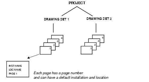
Projects can be (optionally) subdivided into installations and locations. An installation or location does not exist until a drawing page is created and assigned to that installation and location. A page need not be assigned to an installation or location, but it must be associated with an existing project.
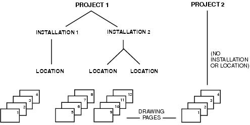
Page numbering need not be continuous; there can be gaps.
Page Storage
When a OpenUtilities Substation drawing page is created and stored, graphical information is stored in a DWG file (AutoCAD version) or DGN file (MicroStation version) while the logical information is stored in the project database.

The DWG or DGN file contains the graphical information for the drawing: everything that is seen when the drawing is plotted.
The logical information for all the drawings in all the projects is stored in the project database which is an SQL/MSDE or Oracle database. This data includes device IDs, wire coordinates, connection information, and much more, and is used by various software functions. By having this information in the database, the software is able to perform project-wide operations such as cross referencing and report generation without having to open and analyze every DWG or DGN file.
When changes are made in the currently open page that affect another page in the project, the software will place the change in the project database. The next time the user opens the second drawing page, the DWG or DGN file is updated from the information in the project database.
Within the DWG or DGN file, the software follows a layering standard that places different types of information on separate layers.
DWG and DGN files are stored in the directory for the project to which they belong.
As each page is created, the software assigns a name to the DWG or DGN files according to the naming format that was defined for the project.
Viewing Pages
The View menu contains a number of functions that control the user's view of drawing pages. Among the relevant functions for OpenUtilities Substation are:
- Redraw: Redraws the current drawing, removing marker blips and display artifacts (stray pixels) left by editing commands.
- Regen: Regenerates the entire drawing and recomputes the screen coordinates for all objects.
- Regen All: Regenerates the entire drawing and recomputes the screen coordinates for all objects in all viewports. It also re-indexes the drawing database for optimum display and object selection performance.
- Real Time Zoom: This option is used for interactive zooming. With this Zoom function, you can zoom in or out of the drawing by holding down the left button of the pointing device and moving the cursor vertically up or down. Press <Esc> to exit this mode.
- Zoom Previous: Displays the previous zoom view of the drawing.
- Zoom Window: Allows the user to enlarge (zoom) the view of a selected area of the drawing. When selected, the software prompts you to select the first corner followed by the opposite corner. This allows you to define a rectangular area on the drawing which will be enlarged to fill the screen.
- Zoom Dynamic: Allows the user to zoom out as well as in. Selecting the function produces a reduced view of the entire drawing with a square area window. Position the area window and click the left button. The window can now be re-sized as desired by moving the mouse. Click the right button to zoom to the selected area.
- Zoom Scale: Allows you to zoom at a specified scale factor. When you select this function you will be prompted on the command line to enter a scale factor. Entering a value followed by "x" specifies a scale relative to the current view ("2x" magnifies objects to twice their current size). Entering a value followed by "xp" specifies a scale relative to paper space units (the first view is considered 1xp).
- Zoom Center: Zooms to display a window defined by a center point and a magnification factor or height. When you select the function you will be prompted to specify a center point and then enter a height or magnification factor.
- Zoom In: Zooms in to the drawing in 2X increments.
- Zoom Out: Zooms out from the drawing in 0.5X increments.
- Zoom All: Zooms to the smallest view that includes everything in the drawing.
- Zoom Extents: Zooms to display the drawing extents. If your mouse has a scroll wheel, turning the wheel will zoom in or out to the point where the cursor is pointing. Pushing on the scroll wheel button twice will zoom to the extents of the drawing.
- Pan (Real Time): This option is used for interactive panning. You can pan the drawing image to a new location by holding down the left button of the pointing device and moving the cursor. Press <Esc> to exit this mode.
- Pan (Point): Moves the view of the drawing by the specified distance.
- Pan (Left): Moves the drawing to the left.
- Pan (Right): Moves the drawing to the right.
- Pan (Up): Moves the drawing up.
- Pan (Down): Moves the drawing down. When you use the Real Time option of Zoom or Pan, you can right-click the pointing device and use the cursor menu to move quickly between zooming and panning. If your mouse has a scroll wheel, pressing and holding the wheel will allow you to pan around the drawing.
- Aerial View: Aerial View is a navigation tool that displays a view of the drawing in a separate window so that you can quickly move to that area. If you keep the Aerial View window open as you work, you can zoom and pan without selecting a command. In the Mode menu you can choose Pan or Zoom. Pan mode allows you to move a rectangle to the part of the drawing you wish to view. Zoom mode allows you to define a window to move and resize the drawing at the same time.
- Clean Screen: Hides borders and toolbars, leaving more room for the drawing area. In MicroStation and PowerDraft versions of the software there is a View toolbar with zoom functions including Zoom In, Zoom Out, Fit View and Pan View.